Wednesday, June 5, 2024

GPS-Enabled Automatic Access Point Placement


The Challenge of Indoor Navigation
Unlike outdoor environments, where GPS technology excels in providing precise location data, indoor spaces pose significant challenges. Traditional GPS signals struggle to penetrate buildings, leading to inaccuracies and poor performance. This has long been a hurdle for implementing efficient wireless networks in large, multi-level indoor spaces. The need for strategic placement of wireless access points (APs) to ensure optimal coverage and connectivity adds another layer of complexity. Achieving even 3 meters of location accuracy indoors has been accomplished with various methods of calibrating the wireless infrastructure or adding in Bluetooth beacons or Ultra Wide Band technology.

Once upon a time, you had to do pirouettes with your laptop in hopes of creating a calibration fingerprint for the wireless environment if you were attempting to get a semblance of location accuracy. See examples: LINK

Demand for indoor navigation has existed but has not always been feasible. Attempts at achieving indoor location awareness have been in place since the early 2000’s. From sprawling malls, hotels, to complex hospital layouts, the ability to accurately pinpoint locations and ensure robust wireless coverage indoors has been achieved in the past with a multitude of overlay networks. Things are finally changing. The latest innovation in this arena is GPS-enabled automatic access point placement, a cutting-edge development spearheaded by leading wireless hardware vendors. I heard about this in great detail at Mobility Field Day 11!
 
Recent advancements have enabled the integration of GPS technology with indoor positioning systems (IPS). Now GPS-enabled access points can auto place themselves on building floor plans. The management system still needs the scale set on the building floor plan and a few known locations to be defined for the GPS-enabled access points to auto-place their neighboring access points on the building floor plan. 

Currently, the Cisco automatic access point placement gives the end user the ability to rotate the access point layout to align with the boundaries of the building layouts within Cisco Catalyst Center. This video from Mobility Field Day 11 features Dave Benham from Cisco Systems explaining how this feature works
 
How It Works
1. GPS Integration: The access points have a GPS chip in it which helps each AP (access points) that can “hear” other access points figure out where they are in relation to each other.
2. Barometric Pressure Sensors: Some access point vendors can even place access points on the correct floor level of the building floor plan by utilizing the data detected by the barometric pressure sensor in the access point. Less barometric pressure is equated to being on a higher floor.
3. Accelerometer Sensor: This sensor can detect the angle at which the access point is physically installed. Ceilings inside buildings may not always be horizontal to the floor elevation, and this angle of installation (when known to the wireless infrastructure) will aide in accurate calculations in the wireless infrastructure system's location tracking algorithms.
4. Automatic Placement Algorithms: Leveraging AI (Artificial Intelligence) and machine learning, the system analyzes the digital map and the gathered location data to determine the most likely accurate placement of access points.
5. Deployment and Adjustment: Once the likely locations are identified, the access points are auto-placed on the digital floor plan within the wireless management system.
Leading wireless hardware vendors are integrating GPS-enabled automatic AP placement into their product offerings, providing businesses with advanced tools to enhance their wireless infrastructures’ location awareness.
 
The integration of GPS-enabled automatic access point placement on digital maps is a big deal for indoor navigation and context awareness. No more pirouettes!

As more wireless hardware vendors incorporate support for 802.11mc, further advancements in the accuracy of indoor location will become possible. 

802.11mc (Wi-Fi Round Trip Time) is an IEEE standard that enables devices to measure the distance to nearby Wi-Fi access points. This high-precision synchronization between peers and round-trip time calculation (Wi-Fi RTT (Round Trip Time)) for location estimation typically results in a reported location accuracy within one to two meters. Wi-Fi RTT has the potential to become a mainstream sub-meter-level indoor positioning technology as more vendors and client devices enable support for this functionality.

Splicing the Red Wire On Your Glowforge for less than $20


If your Glowforge laser suddenly stops emitting the laser but all the other functions seem to be normal (your laser powers on, the print head centers, focuses, moves back to home base, the print head goes through the motions of printing your project but no laser marks are being made), you may have a short in the high-voltage red wire that runs under the glass laser tube. Here is a link to a helpful video for locating the red wire in your Glowforge.

If you have a short in your red wire, it will look something like this:
IMG_2174

The red wire runs under the glass laser tube, snug in an aluminum channel where the wire does not move, nor does it come into contact with anything else moving (that I can see). On the far right side of the laser tube (the side with the on/off button), the red wire is screwed to the metal laser tube "cap" with a 10m hex screw. Follow the disassembly instructions in the video above to remove the glass top side pieces from your Glowforge in order to access the attachment point of your red wire. Some Glowforge units ship with a black fiberglass protective sleeve over the red wire, but there have been reports of the red wire shorting out even through the protective sleeve.

Some users have reported success with using liquid electrical tape and a layer of heat shrink to repair the shorted wire. I used this repair method at first but only succeeded in 15 minutes of laser use before the wire shorted out through the repair in the same spot.

Steps to disassembly of the Glowforge to repair (splice) the red wire
  • Unplug your Glowforge Laser
  • Remove the three 10m hex screws from each of the glass top sides and remove the glass top sides
  • Remove the red silicone cap from the end of your laser tube
  • Remove the 10m hex screw from the red wire ring connector
  • Tie a sturdy piece of string/twine/curling ribbon to the ring connector on the end of your red wire.
  • Locate the red wire on the left side of your laser tube and slowly remove the red wire from the channel that runs under your glass laser tube
  • You may want to reroute your red wire under your glass laser tube someday. If you think you might want to do this, leave the twine in place and secure it so that you can pull another wire back through this channel without having to disassemble your whole laser.
  • Cut your red wire at the section where it shorted out. Remove small amounts of the wire until you reach a solid section of the wire and insulation.
  • Strip off 0.5 inches (half an inch) of insulation from your red wire.
  • Route your red wire through the aluminum hoop if possible (for cable management)
  • Slide one of the white plastic insulator pieces onto the left wire (tapered end of the white insulator to the left, threaded side to the right
  • Tin the end of the wire with a soldering gun and solder.
  • Loosen the screw on the small off-white connector piece
  • Insert the tinned wire into the small connector piece
  • Tighten the screw on the small off-white connector piece
  • Route the right hand side of your red wire as needed and affix the 10m hex screw to the end of the laser tube
  • Slide one of the white plastic insulator pieces onto the left wire (tapered end of the white insulator to the left, threaded side to the right
  • Tin the end of the wire with a soldering gun and solder.
  • Loosen the screw on the small off-white connector piece
  • Insert the tinned wire into the small connector piece
  • Tighten the screw on the small off-white connector piece
  • Thread the two larger insulated pieces together and tighten them by hand.
  • Ensure that the spliced wire is not making contact with the back of your laser unit by gently moving your laser tube assembly to the back of your unit with your hands.
There is a high-voltage splice kit available for purchase on Amazon (it is a two-pack of splice connectors even though you'll only need one splice connector assembly). If you want your kit fast, Amazon is the way to go—but you'll be paying $15 for the parts. If you have patience, you can order a similar kit from AliExpress for $2.

The center hole of the off-white hard plastic splice ends will need to be enlarged with a drill bit to accommodate the width of the Glowforge red wire. You will not need the black rubber end caps when you assemble your splice. The black rubber caps will not fit the Glowforge red wire and are extremely difficult to enlarge with a drill bit as they are made from rubber.

You can optionally apply two layers of heat shrink to the left side of your red wire where you have routed it through the aluminum "tray." When you reroute your red wire through the oval hole in the aluminum laser tube tray, you may desire a protective layer where the wire will rest against the somewhat sharp edge of the aluminum tray. We used two layers of heat shrink at this junction, just in case.

The aluminum "hoops" that run across the top of your glass laser tube DO NOT need to be removed for you to route your red wire through the rear side of the aluminum hoop. You'll use this hoop for your red wire cable management. Running your red wire through this area will ensure that your wire does not droop and possibly get in the way of your machine's running. The red wire will fit through the aluminum hoop in the space on the rear side of the glass laser tube.

If you have to repair your red wire again (if you get another short in the wire), you may find it better to replace the end of the red wire that screws to the right-hand side of your laser tube with a section of this wire. You'd have to recreate the ring connector end by stripping the insulation, tinning the wire, and crimping on a ring connector, and covering that in heat shrink tubing. Replacing the red wire would allow you to re-run your red wire back in the original channel under the glass laser tube and have the splice connectors tucked away, out of the way somewhere on the left side of your laser.


There will soon be a kit available with the replacement wire, splice kit, etc, and a how-to from a member of the Friendliest Glowforge Community on FB, but it is not available online at this moment.

Saturday, September 16, 2023

Jacquard deColourant + Laser Engraving


I've recently integrated Jacquard deColourant into my concepts/creations. The deColourant is a non bleach chemical that non-destructively removes the dye from darkly colored natural fabrics that have been dyed with a "dischargeable" dye . It allows you to create a white area on a dark shirt that you can then apply your image to. It works by being sprayed, brushed or stamped onto the dark fabric, allow it to dry and then apply steam heat from an iron and the fabric turns white!! If the deColourant is spilled on a surface where you do not want it to be, just wash the garment in that area (or the whole thing) because nothing happens until you apply heat.

In the Amazon reviews for the 8oz bottle of the deColorant, Dennis S. mentions using his laser etcher tool at high speed and very low power to create an image in the area where he applied the deColourant. Using this directed heat method is the same concept that's used in fax machines and thermal paper. You'd use your laser etching machine to "etch"/heat a negative image into the deColorant area. I haven't seen anyone else anywhere mention using a laser engraver as a pointillized heat source to be used with the Jacquard deColourant. His results are amazing and show the potential of what is possible.

I received a second hand Glowforge Pro for my birthday & dug into how to achieve something similar to the image from Dennis. I cut up a spare t-shirt, coated it in a layer of DeColourant, let it dry and then started running test strips. I was trying to max out the speed and run the job at the lowest speed, based on what little Dennis included with his photo. The thing I didn't know at the time was that when the Glowforge is set to the highest speed, the size of the laserable area is reduced (a smaller canvas area). This means that my excellent test data is somewhat invalidated because I want my final image to be bigger than the area that is available when the Glowforge is running at 4000 speed. Also, some of the higher speed settings aren't available depending on the file type being used to engrave. No, I haven't read the manual yet, but I'm working on it as I bump up against hurdles like these. The test sheet below required further adjusting to balance the "canvas area" with the available speeds/powers.


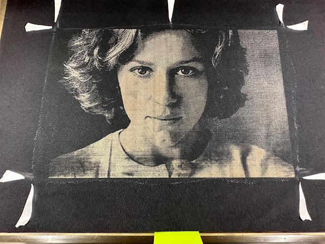
My findings to date. These settings achieve a good reduction in the shirt color where the laser hits the deColourant as applied to the shirt. I used white masking tape cut into arrows to indicate the corners of the rectangle where I applied the deColourant to the shirt so I can see the rectangle where I want to "print" the image in the Glowforge preview of the bed image.

Using a PNG vs a SVG achieves minimal reduction in laser "print" time. I see no benefit in using an SVG over a BMP or a PNG for this use case.

Glowforge Settings for reliably good "prints"
Speed 2600
Precision Power 15
(sometimes I think my power settings are a bit hot, but when the shirts are washed, they look fine)
Grayscale Vary Power
Min Power 3
Margin Optimization 100%(maximize quality)
Lines Per Inch 225
Number of Passes 1 pass
Focus Height Auto

I would like to speed up the process and will look into how I can increase the "printable" image size and achieve higher laser speeds.

I used the tutorial by Bailey (MyDogsThinkImCrazy) to make magnetic risers & use a magnetic erase board as an adjustable surface rather than having the crumb tray in place inside the Glowforge. She gives the background on the 3D printed risers and the magnetic whiteboard & ceramic magnets to use here.

The different heights of risers are to be used when engraving in items that wouldn't fit in the Glowforge if you were using the crumb tray. This is her post on engraving things without the crumb tray. Using the risers allows me to tuck the extra fabric of the t-shirt underneath the magnetic white board and secure it in place with a few magnets & painter's tape on the bottom of the magnetic white board. Ignore that the rectangle where the deColourant was painted looks grody. It doesn't matter in the slightest when it is getting lasered. It does help to dry the area a bit with a hair dryer set to COOL no heat (deColourant is heat activated). I've tried lasering deColourant when it was still wet and I was getting inconsistent results.


My risers are made out of scrap wood (I don't have a 3D printer), glued and stacked to achieve the various heights of risers (1.4, 1,2, 1 and .8 inches high) I engraved one layer and cut out a circle in one layer to have enough room for the thickness of the magnet to be flush with the wood of the riser (the magnets are .2 inches thick).


The Cricut cutting mats have a similar grid layout to help you place your vinyl and the things you're cutting - the Glowforge does not have this X,Y location feature - but the post by Bailey tells you how to make your own grid and then the aberration from the Glowforge fish eye bed lens will not affect the accuracy of your desired cuts/engraves/scores. In this post she includes a PDF that shows how you can make your placement jigs for the grid board out of universal interlocking plastic bricks!

I paint on the deColourant with a small paint brush, being sure to saturate the fabric of the shirt. I then use a hair dryer on the NO HEAT setting to dry the deColourant before placing the shirt in the Glowforge. Most of the shirts I've made take anywhere from 30 - 60 minutes to fully render (line by line). If the power settings were lower or the image were smaller or I were printing at a lower lines per inch measurement the process would go quicker. 

Here is a photo of what I'm calling successes with deColourant and the Glowforge. I'm pleased with how these shirts have turned out and as I work with these two tools more, I'm certain that I will learn more about what images transfer best with deColourant and how I can adjust the image and Glowforge settings to get the best "print."

Shirt blanks from PressHall.com 
5000 Gildan 5.3-ounce 100% Cotton T-Shirt <-turned out well, lightened to a grey
PC54 Port & Company Core Cotton T-Shirt <-turned out well, lightened to a grey

DT6402 District Women's V.I.T. Boxy T-Shirt <-nice soft fabric, lightened to a sepia tone

Jacquard SolarFast UV Reactive Permanent Dye - How To and Lessons Learned

I'm late to the Jacquard SolarFast game. I've recently discovered this method for transferring images to clothing. I got started down this path via an Instagram post about printing on fabric with the Cyanotype process. Further research turned up the Jacquard line of SolarFast dyes in a plethora of colors. 

I've been hankering to make my own rendition of the Blue Velvet t-shirt I had in the '90s and a new incarnation of the infamous Robert Watts/Products for Implosions // Vivienne Westwood/Malcolm McLaren Seditionaires "tits" tee (link & link).

As luck would have it, I have 3M transparency sheets, an HP Laser Printer and access to lots of Florida sun.

I've also been able to utilize the artwork I've made for other projects and print transparencies to use with the SolarFast dye. Bonus!

The basic concept of the SolarFast dye is to brush it onto the t-shirt with a foam brush or a paint brush in a room protected from UV light sources (daylight, incandescent bulbs). If you use a paint brush, you will likely see brush strokes in your final work unless you take care to fully saturate the t-shirt with the Solarfast dye. The Jacquard website is your first resource for tips, tricks and general instructions.

Notes I've picked up along the way are:
  • You can thin the SolarFast down with water to a 1:1 ratio without losing more than 10% of the final color vibrancy.
  • The 1:1 ratio can be used in a spray bottle to spritz the tshirt in preparation for sun exposure. This worked ok, but I prefer the control of a paintbrush.
  • I've used my Cricut to cut a mask for the shirt using the Reynolds Freezer Paper stencil method. This keeps the area where I'm applying the SolarFast constrained to only the shape that needs the dye. Lots of tutorials show the person painting a big square of the dye but only exposing a small area of this dyed fabric to the sun. My goal is to mimic a silk screen effect and only lay down SolarFast where it really needs to go. This will also reduce the amount of area you need to wash the unexposed SolarFast from once your garment is ready to wash.
  • Pouring the SolarFast into a bowl and using a small paintbrush is the easiest method to paint your fabric with SolarFast.
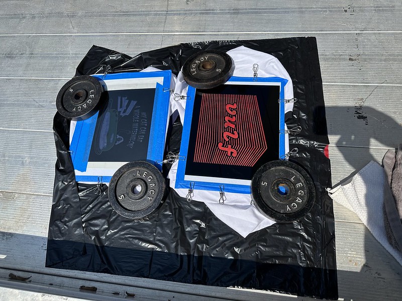
  • I've made good use of last year's corrugated plastic campaign signs as backing boards to clip the shirt to and used a piece of cardboard inbetween the front and back of the shirt to keep the SolarFast from bleeding through to the back of the shirt.
  • When you're preparing your images for printing on the transparency sheets, use registration marks outside the boundary of your artwork to align your two prints quickly and easily. Using two transparency prints will give you a fully opaque negative to get greater contrast in your SolarFast prints.
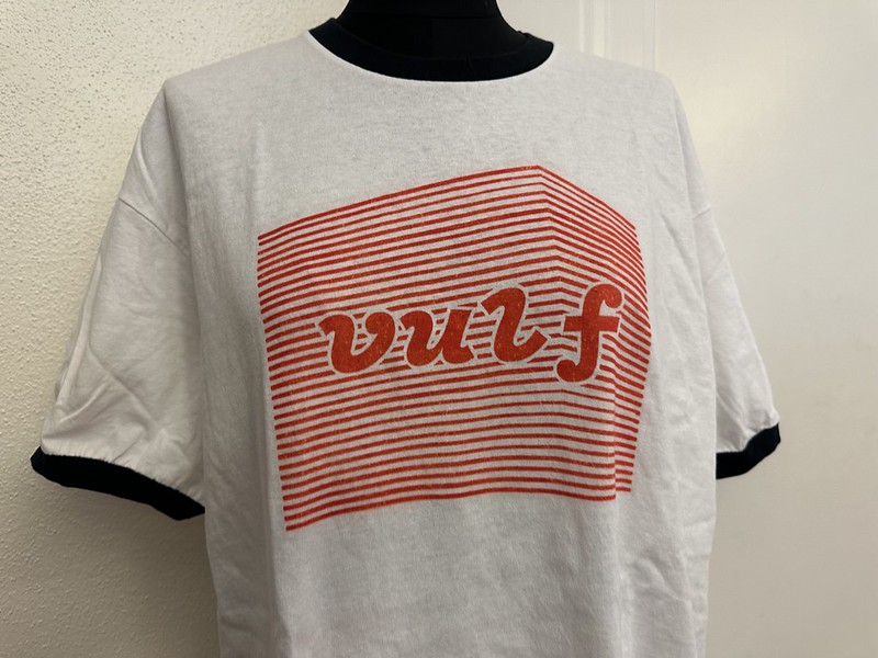
Below are photos of the application of the SolarFast dye, placement of the transparency, the exposure process and the final product.

IMG_7656
IMG_7660
IMG_7861

Tuesday, July 5, 2022

Computerized Machine Embroidery with the Brother Innovis VE-2200 using Inkscape and Inkstitch


Bear with me, we are about to go down a rabbit hole that begins with a birthday present and ends with a slew of Wet Leg patches.

Last September (2021), my husband gave me a most excellent birthday present. He found a second hand Brother Innovis VE-2200 computerized embroidery sewing machine. At that time, I was finalizing the Fred Lane, Elvis Costell and Peter Weller puppets I'd been making. The machine sat on the floor of my workspace for a couple of weeks til the work table was free. While I was finishing the puppets, I was searching the internet for software capable of creating files the VE2200 could stitch. The majority of options were very expensive (not a desirable option) and were not available on the file trading networks (imagine that?!). I stumbled across mention of Ink/Stitch as a plugin for Inkscape and that the whole software package was free and open source. Free and opensource is often code for amazingly hard to learn, and with documentation that requrires a LOT of knowledge of writing code. Luckily this wasn't the case with Inkstitch.

The lovely father/daughter duo Project Anonymous on YouTube got me set off in the right direction. I watched the tutorials created by Ink/Stitch to fill in the technical gaps I had and from here, my first project was to recreate the floor mat logo patch for the Nissan PAO. I must've spent at least 9 or 10 hours working on the PAO logo, trying to figure out the intracacies of the Bezier tool, how to separate the thread into color layers for ease of stitching etc. At one point, I lost 6 hours of work because I'd been saving my work in a .pes file instead of an .svg file. The .pes file is used by the machine for stitching, but the .svg file is the one that is editable and re-workable and THEN saved as a .pes to stitch.

I moved on from the PAO logo to stitch versions of the Pike Factory cars, then I recreated the Kraftwerk heads from the Musique Non Stop video to put on the back of hoodies. From this exercise, I learned that recreating the artwork is much faster than cleaning up the software interpreted artwork. Also, there is a high value in having one contiguous running stitch or bean stitch to speed up the stitching process. The software tool 'trace bitmap' netted me a stitch count of 118,754 (nobody's got time for that mess). When I re-drew the wire frame heads (a task I desperately did not want to do but HAD to if I wanted it to stitch right), my stitch count went down to 36,6345. Much more manageable.

Next stop from the UV reactive thread in the Kraftwerk embroidery was GLOW-IN-THE-DARK thread. Oh my! I created patches from some of the neighborhood buildings and made a line of "Seminole Heights After Dark" patches which all glowed in the dark, reacted to UV blacklight, or BOTH.

It was around this time that I became aware of the band Wet Leg from the Isle of Wight through the "Now Playing" group I'm a member of on Facebook. Around May of 2022, the group was blowing UP with posts from people spinning their Wet Leg lp in all the colors it comes in. It turned into a group meme of sorts, becoming a running gag. Well, I had to go give it a listen simply due to the fact that I'd never seen a single LP get so much attention from this FB group, ever.

Wet Leg are Rhian Teasdale, Hester Chambers, bassist Ellis Durand, drummer Henry Holmes, and guitarist Joshua Omead Mobaraki with a new album out on Domino Records as of April 8 2022.

I gave it a listen and liked it (a lot!)  - then my friend Daniel in Orlando posted that Wet Leg was coming to The Plaza in Sept. I secured tickets and while I was doing that, I found this photo of Wet Leg with Rhian Teasdale wearing a jacket covered in vintage Americana trucker PATCHES. Holy smokes what a venn diagram.


I thought OH MY! I can replicate these vintage patches and maybe someone will want new ones?! So I started with the I'm a truckers' girlfriend, then the Truckers Make Better Lovers and finally the Next to Sex my CB Radio is best. Well, it seemed nobody wanted replicas of vintage trucker patches. I found the FB Wet Leggers (Wet Leg Fan Community) and posted in there about my replica trucker patches on May 24th. Crickets..

Late on the evening of June 1st, I had an idea to make a patch of Wet Leg lyrics (Excuse me, (what?)) by using the letters I'd already digitized in the CB Radio patch. The "font" in the CB radio patch is pretty cool and I only had to make the letter "c" to do the patch. I stitched up 3 of them and posted to the group - did anyone want these and I'll mail them to you with a stamp if you do. HOLY SMOKES. I think I shipped out at least 15 or more Excuse Me What patches for free. Clearly people want patches BUT they want patches that represent something NEW. Suggestions kept coming in from the group and I used the foundation of the first 3 patches I'd made to create new patches. By June 6th, I had 7 different Wet Leg patch designs and a handful of my patches were in the mail to places all over the globe.

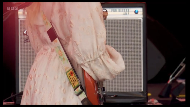
When Wet Leg played the Glastonbury Festival June 24th, Hester's guitar strap was decorated with one of my "I feel sorry for ur mum" patches!!! 


The suggestions from the Wet Legger's group kept pouring in and I kept making patches. To date (July 5th) there are now 22 different Wet Leg patch designs! I'm keeping records of patch and sticker sales so that I can pay the profits forward to the band (perhaps when they play The Plaza in Orlando). Until then, I'm working on creating the embroidery for the uniforms they wear in the UR MUM video as well as sourcing badges and recreating the Isle of Wight patch on the left sleeve of their Angelica's uniforms.

Through this process of rapid fire creation, I've learned that it is good practice to take the covers off your VE-2200 and clean out the flurf and thread bits that will cause your machine to sew badly. It is also best practices to use T-Pins to hold the fabric really taut in the large embroidery hoop as this minimizes fabric shrinkage as the embroidery stitches pull the fabric tighter. I have learned that auto-routed satin columns are your friend and are not to be feared as they will minimize the amount of post-stiching clean up you'll need to do (trimming jump threads) and auto-routed satin stitches also make the projects stich faster overall. I have learned that the large (12x7in) hoop has to have it's screws REALLY tight or the machine won't recognize it as a hoop (this realization was had during a call to Brother's tech support). It is also good to pre-cut your HeatNBond backing to a uniform size, to minimize the need to trim the edges.

I've gotten much faster at digitizing images and getting them to a stitchable file. I recently made three patches from photos of people and got to a completed patch after investing about an hour into each of them. This is a timelapse (sped up 10x) of the processes I go through when turning a picture into a SVG/PES file.

Also, this is the basically the best birthday present ever. It's the gift that keeps giving! Thank you DAVID!!

Here's a link to my ETSY shop!! https://www.etsy.com/shop/JenniferHuber


Monday, October 18, 2021

Elvis Costello and Paul Weller as Puppets!


What happens when you catch me in the moment of being on a puppet making tear (having just shown off the newly minted Conny Plank puppet) and a dear friend says "IF I had any artistic ability whatsoever there would be Elvis Costello and Paul Weller ones.  They could fight for my heart, like Karate Kid.  Also if I wasn’t lazy.  Also if it wasn’t your brilliant idea."

Well, I said CHALLENGE ACCEPTED.

So it began.

Making the Small Fry body was the easiest part. The pattern is quite simple and I was already in the process of sewing one other caucasoid puppet, so adding two more to the batch actually made the process go smoother. Two I sewed together by hand and the third one I sewed on the sewing machine. Machine sewing the Small Fry body turned it into a nearly complete puppet (body, hands, legs, and feet) in just over 3 hours. Someday I'll learn the Muppet ladder stitch, but so little of their face seams are even going to be visible on these two puppets, I didn't sweat it too much.

I started on Elvis first because, in my opinion, he's pretty straightforward with regard to his visually recognizable markers. His teeth, oversized glasses, and excellent hair make it easy to turn him into a recognizable puppet. The part I was finding challenging was deciding WHICH LOOK to use as the guideline for his hair and clothing. Rocky said for him that decision was easy - the look he's got on the This Year's Model album cover. GOSH THAT'S EASY. Now I had something to work with for Elvis's clothing. Black suit, white button-up shirt with tiny grey polka dots, and a grey satin tie.


<insert image of this year's model cover>

I looked around online for suitable patterns for 18" dolls (they're comparable in size to the Small Fry puppet) and ended up buying a couple of patterns. There isn't much out there for Small Fry clothing patterns (yet) so I got to sewing and modifying the 18" doll patterns. The biggest issue with a pattern for an 18" doll is that the doll has a NECK and the Small Fry doesn't. Shirts and jackets don't fit as cut on the first try. I made a few mock-up dress shirts until I'd modified the dress shirt pattern well enough to look right and close at the top collar button on a Small Fry puppet. Here is a link to the Small Fry puppet patterns I've created through trial and error. I've included all the sewing instructions for the dress shirt and blazers.


I sculpted Elvis's teeth out of some FIMO I had leftover from making puppet noses for Kraftwerk. It wasn't going to matter that they were not teeth colored color to start with. I scoured the internet for good photos of his nose and sculpted a tiny nose for him. Then thinking it might be handy to have a small reproducible puppet nose, I made a mold of it and used it for The Reverend Fred Lane puppet. I did a DIY flocking of the sculpted/cast nose to make it blend with the puppet fleece skin once the nose would be attached to the puppet face.

Elvis Costello's teeth and nose


I painted his teeth using acrylic craft paint I had on hand. The paint probably won't stand up to lots of abuse over time, but I don't anticipate that Rocky has a lot of hard use in mind for his Elvis puppet. While I was daydreaming about how I was going to affix Elvis's teeth to the puppet mouth I decided I didn't want to make them permanently attached so I made a new puppet and puppet mouth plate and used some small round magnets I had on hand to make Elvis's mouth plate attach the teeth MAGNETICALLY. I cut and glued little strips of magnetic metal to the backside of the upper and lower teeth. The magnetic teeth work like a champ. I'm thrilled.

Redoing the mouth plate (and puppet body) to make the teeth magnetically attach!

On the cover of This Year's Model, Elvis is standing behind Chris Gabrin's (the album photographer) Hasselblad 500 camera and tripod. As luck would have it, some scouring of the internet turned up a papercraft pinhole camera model of the Hasselblad 500. The original creator of the papercraft is Kelly Angood but her site doesn't host the file any longer. I found it on Scribd. I printed out the Hasselblad at an appropriate scale for the Small Fry puppet, making the camera dimensions around 1.5 inches. Putting the papercraft together was tedious, but I was happy that I wasn't trying to make a tiny, functioning pinhole Hasselblad 500.  

Papercraft Hasselblad 500

I measured the lens diameter needed and poured 4 exploratory lenses out of clear two-part resin. The first one worked like a champ. I did a light sanding to the edge of the lens so the UHU would hold it in place and then I googled to see what kind of aperture the Hasselblad has. I was on the fence about making it look exactly like the album cover, or making it true to life. I chose true to life. I printed out and cut the leaf aperture opening and glued it to the lens.


Papercraft Hasselblad 500 lens with leaf shutter

Now that the lens was in place, I made the rear of the camera attach with magnets and inserted a stabilizing base and threaded nut for a tripod mount inside the camera. Once the glue was dry, I painted the inside of the camera black (why not?).

Papercraft Hasselblad 500

I went looking on eBay for a Small Fry sized tripod that looked similar to the one on the album cover. I scored with a nice vintage Escot tripod in black/chrome with a handle that looked quite a lot like the one on the cover.

Papercraft Hasselblad 500 comparison photo

I completed his jacket with three working buttonholes and then cut his hair out of coal Mongolian faux fur from PuppetPelts.com (leftover from the Kraftwerk creations). I then attached his eyes, nose and then gave him a haircut.

Elvis Costello - looking good

Another search of eBay turned up a pair of perfectly sized, childs' hornrimmed glasses. When they arrived, I used some loose lenses from broken reading glasses to give Elvis's eyeglass frames something to hold onto and reflect the light.

Elvis Costello - yassssss

With his clothing, camera, glasses, and tripod complete, I was able to recreate the UK, US, and Swedish release album covers of This Year's Model.

UK Cover


Elvis Costello This Year's Model 

  US Cover

Elvis Costello This Year's Model

Swedish Cover

Elvis Costello This Year's Model

One more scouring of the internet turned up Axman - a woodworker in the UK who makes replicas of famous musician's guitars, including Elvis Costello's iconic Jazzmaster guitar (!!). Take my money, right?

Elvis Costello PUMP IT UP

The hard part was shooting a video of Elvis to replicate a tiny portion of the Pump It Up video. Green screen is hard y'all. Trial and error, shoot, re-shoot and then spend an inordinate amount of time in Adobe Premiere Pro masking around his feet to avoid reshooting again. I'm happy with how it turned out and it makes me laugh hysterically! That was the goal all along. 

I didn't send Rocky any process photos once I'd shown him a shot of the teeth pinned into place for a trial fitting (!). Keeping the pictures I've taken off the 'net and hidden has been sooo hard because I've been wanting to share each success I've had in this creation.

Here is the final video cut of puppet Elvis in all his glory in the Pump It Up video!


Creating a Paul Weller puppet was much less challenging by far. I found a tiny doll wig on AliExpress, made it a bit smaller by running a long stitch up and back around the scalp of the wig to "tighten it up" and make it fit the Small Fry better. I picked one of Paul's least-bad haircuts to give the puppet. I didn't have the heart to give him a severe hairline like I saw in most of Paul's earlier photos.

I found a tiny Fred Perry polo shirt on eBay, tailored it to fit Paul, and made him a pair of dark pants.

Paul Weller lookin spiffy!

Shoes were found on AliExpress and modified to be more like suede boots.

Paul Weller's tiny suede boots

I made Paul's nose a more traditional puppet nose - a bit of foam wrapped in fleece and sewn in place. I did some searching to see if he has a signature guitar strap (he does) and I made a tiny guitar strap to match the "real" one.

Paul Weller

I learned a lot in the creating of these puppets and I'm happy to have sent them to their new owner! I can't wait to see what Rocky does with Elvis and Paul!!


Wednesday, September 15, 2021

How To Make A Skydancer Tube Man (Tube Person)


Perhaps you've always wanted your own custom Skydancer but didn't know how to make one? Look no further. I will tell you how I made this Skydancer and what all of the measurements are and where I sourced the fabric and fan.

This drawing isn't exactly to scale, but it has all the measurements of the Skydancer you see pictured above. I also made one to model Wolfgang Flür from Kraftwerk. Here's the measurements for that Skydancer.

Kraftwerk Skydancer Measurements
If you have a serger sewing machine, making a Skydancer is fairly straightforward with this pattern. I used the Vitruvian Man drawing by daVinci as the source for the proportions between head/face/torso. The proportions work regardless if your Skydancer is wearing "clothes" or not.

This Skydancer pattern will create a Tube Man somewhere between 14-15 feet in height. Measurements are indicated in inches on the pattern and the process photos below will assist you in placing the openings for the Tube Man arms.

I ordered the 1.9 ounce ~70 denier ripstop nylon from HERE, the waterproof 600 denier fabric from HERE, and the 2-inch wide hook and loop (you'll need the loop side as the fan will have the hook side pre-attached to the circumference of the fan base) from HERE. The fan I have is a Big Bear B-Air BB1 but the current model is a BB3. Total cost of fabric + the fan is around $289. Given that custom Skydancers are priced around anywhere from $100 - $200 not including the price of the fan, you could easily make your own or hire the services of a local person with a serger sewing machine like mine to make the Skydancer for you. I have a JUKI MO 654DE but any serger type sewing machine will work for this project.

The ripstop nylon is 60 inches wide which is exactly the same circumference as the base of the B-Air fan. Create a thicker bottom attachment section with the 600 denier waterproof canvas. This is the section you will sew your 2-inch loop fastener strip to in order to connect the base of your Skydancer to the B-Air fan.

IMG_2422 

 I used a small salad plate (12 inches in diameter) to mark the arm openings. The arms taper to a 4-inch opening. The center of the "armpit" is 14.25 inches from the back seam (the fabric width including the selvage was 61 inches wide).

Here is what the loop strip will look like on your canvas bottom section. Sew a 60-inch strip around the base of the canvas section and then attach a hook and loop strip to each edge of the canvas 12 inch by 60-inch section to secure the canvas fabric closed once you've attached it to the base of the fan.

IMG_2415

You can make the facial features out of the same ripstop nylon, serge the edges and sew them by hand to the Skydancer as seen here:

IMG_2443

Here is the pattern for a basic Skydancer/Tube Man

SkydancerMeasurements
Here is the Skydancer in action!!